Homelab, 2024 stage 1 Networking
updated 2024-04-28
Stage 1 Networking
The backbone of the homelab will be the Network. In a US residential property, there will be a commercial telecommunications company that provides connection to the internet. This will vary based on where you live in the world.
Once you have access to the internet, you need to connect your devices to a private network that shares access to the internet through your gateway.
Private networks refer to networks that are restricted in access, typically within a specific organization, such as a business, educational institution, or government agency. These networks are designed to be accessed only by authorized users or devices, offering a higher level of security compared to public networks like the internet. Most people do not realize that their internet service provider sets up a private network for them. For a homelab, you control the network rather than a business or other institution. Here are the basics:
-
Access Control: Access to a private network is restricted to authorized users or devices. This is typically enforced through authentication mechanisms such as usernames and passwords, digital certificates, or biometric authentication. Additionally, firewalls and other security measures are often employed to prevent unauthorized access. Even the gateway/router that your internet service provider gives you will use a firewall by default.
-
Security: Security is a primary concern in private networks. Various security measures are implemented to protect the network from unauthorized access. This may include encryption, intrusion detection/prevention systems, virtual private networks (VPNs), and regular security audits. Even if you do not store sensitive information in your lab, you likely do not want anyone in the world to access your network much like your private home.
-
Infrastructure: Private networks can be built using various networking technologies, including Ethernet, Wi-Fi, and fiber optics. These networks may include routers, switches, access points, and other network devices to facilitate communication between devices.
OSI model
The OSI (Open Systems Interconnection) model is a conceptual framework that standardizes the functions of a telecommunication or computing system into seven distinct layers. The OSI model serves as a guideline for understanding and implementing network communication protocols, enabling interoperability and standardization across diverse computing environments over the whole world.
Each layer serves a specific purpose in facilitating communication between devices over a network. Starting from the bottom:
- Layer 1, the Physical layer, deals with the physical transmission of data through mediums such as ethernet cables or wireless signals.
- Layer 2, the Data Link layer, manages data framing and provides error detection and correction mechanisms. This layer represents protocols such as Ethernet, Wi-Fi, bluetooth, and newer protocols such as Z-wave and Zigbee. ISPs commonly use Point-to-Point Protocol (PPP) to grant your router access to the internet.
- Layer 3, the Network layer, handles packet routing and forwarding based on logical addresses (e.g., IP addresses).
- Layer 4, the Transport layer, ensures reliable data transmission by establishing, maintaining, and terminating connections between devices. Although not developed under the OSI Model and not strictly conforming to the OSI definition of the transport layer, the Transmission Control Protocol (TCP) and the User Datagram Protocol (UDP) are commonly categorized as layer 4 protocols within OSI.
- Layer 5, the Session layer, manages communication sessions between applications. I view this one as more abstract but this is the layer where you control how long you should open a “persistent” session between a client and a server. For example, if your connection is interrupted, the session layer may be able to re-open a layer 4 transport connection to continue your session. If we are transferring a large file over the network, we want to ensure that we re-use the same session until the transfer is completed regardless of interruptions.
- Layer 6, the Presentation layer, handles data translation, encryption, and compression. An example may be converting binary encoded text file into human readable UTF-8 format. Many applications do not distinguish between layer 6 and 7. For example HTTP is regarded as a layer 7 protocol but it includes aforementioned encoding features for text/character formatting.
- Layer 7, the Application layer, provides interfaces for user applications and network services. This is where you find many different protocols related to exchanging data between applications running on different systems over a network. Examples include HTTP, Telnet, SSH, FTP, SMTP, and DNS.
Networking services
In most home environments, a consumer router purchased off the shelf or one provided by an ISP (Internet service provider) will provide several services in addition to internet access. Before devices can receive and transfer data, the router needs a mechanism to determine what devices are on the network and how to route traffic to and from each device. For example, if you want to play a video on your smart TV, the router needs to know how to send data to your TV instead of another device on the network.
MAC and IP
A MAC (Media Access Control) address is a unique identifier assigned to network interfaces by the manufacturer, providing a hardware-specific address for devices within a local network segment. Every device that is connected to the network will have a unique MAC address. Some mobile devices such as phones and laptops will “spoof” a different MAC address for every network that they connect to. The idea there is to prevent tracking your device across all of the networks that it connects to. This would be layer 2 of the OSI model.
An IP (Internet Protocol) address is a logical address assigned to devices on a network, used for identifying and communicating with them across interconnected networks. This would be layer 3 of the OSI model.
Internet Protocol version 4 (IPv4) defines an IP address as a 32-bit number. This is represented in dot-decimal notation with 4 groups of 8 bits. However, because of the explosive growth of the internet globally, a new version of IP (IPv6), using 128 bits for the IP address was created. IP addresses are written and displayed in human-readable notations, such as 192.168.1.1 in IPv4, and fdff:ffff:ffff:ffff:ffff:ffff:ffff:ffff in IPv6. To represent a 128 bit value, IPv6 addresses are eight groups of four hexadecimal digits, each group representing 16 bits.
The IP address space is managed globally by the Internet Assigned Numbers Authority (IANA), and by five regional Internet registries (RIRs) responsible in their designated territories for assignment to local Internet registries, such as ISPs, and other end users. Some IPv4 addresses are reserved for private networks and are not globally unique. So without these institutions, it may have been impossible to connect to someone in another country if we did not all agree to the same standards.
IP addresses are used for routing packets across networks, enabling communication between devices regardless of their physical location, while MAC addresses are utilized within local networks for addressing and delivering data packets to specific devices within the same network segment. Devices use ARP (Address Resolution Protocol) to map IP addresses to MAC addresses within their local network.
To find your MAC and local IP address, there are terminal commands for the most popular operating systems:
Windows: ipconfig
macOS: ifconfig
Linux: ip address or ip a for short
ARP
Address Resolution Protocol (ARP) operates on a router by facilitating the mapping of IP addresses to physical MAC addresses within a local network. When a router receives an incoming packet destined for another device on the same network, it checks its ARP cache to determine if it already knows the MAC address corresponding to the IP address of the destination device. If the MAC address is not found in the cache, the router broadcasts an ARP request packet to all devices on the network, asking for the MAC address associated with the target IP address. The device that owns the IP address responds with its MAC address, allowing the router to update its ARP cache. Subsequently, the router can forward the packet to the correct destination using the discovered MAC address. ARP plays a crucial role in enabling communication between devices within the same local network segment, facilitating the efficient routing of data packets based on their destination IP addresses.
This data is not encrypted. You can view the ARP cache from a computer with terminal access. On windows, usually you just enter the command arp.
On *nix devices, you can enter the command arp -a to view the results for all network interfaces.
DHCP and DNS
Dynamic Host Configuration Protocol (DHCP) and Domain Name System (DNS) are fundamental networking protocols that play crucial roles in modern computer networks. DHCP automates the process of assigning IP addresses to devices within a network dynamically. Instead of manually configuring IP addresses on each device, DHCP servers automatically lease an IP addresses from a predefined range to devices when they join the network. The alternative is to configure each device with a static IP address but you must ensure that you do not use the same IP address for multiple devices. DHCP prevents collision of IP addresses.
DNS is a distributed naming system for translating domain names (like example.com) into IP addresses (such as 192.168.1.1) that computers understand.
DNS resolves human-readable domain names to machine-readable IP addresses, enabling users to access websites, send emails, and connect to other networked resources using memorable domain names rather than numeric IP addresses. Together, DHCP and DNS form the backbone of modern networking infrastructure.
Network infrastructure
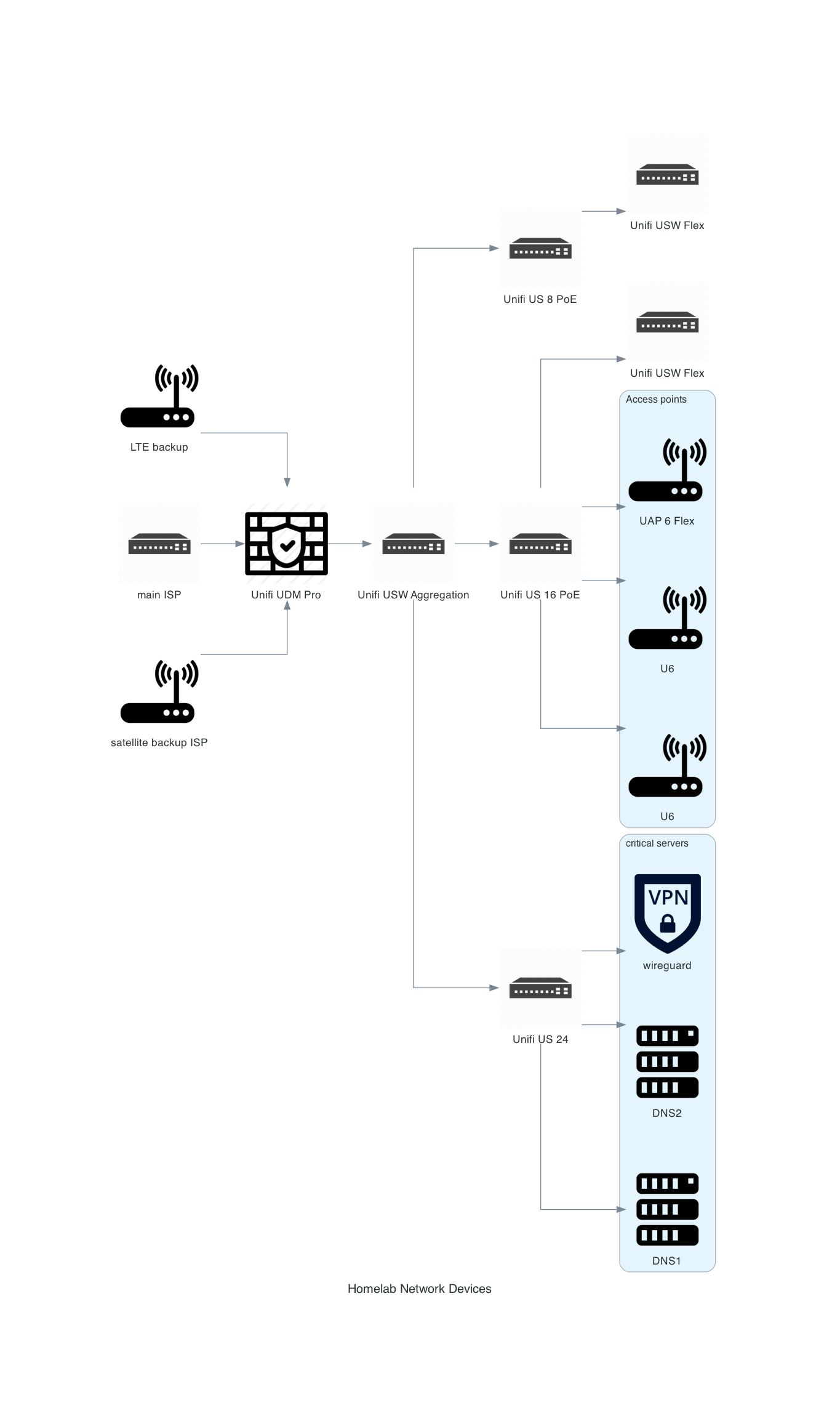
For my homelab and home network I will be using Ubiquiti Networks equipment in addition to what my internet service provider installs.
I have been working remotely for my career since 2020. I also live in a house and want to ensure the house maintains a security system and monitors for emergencies such as fire and flooding.
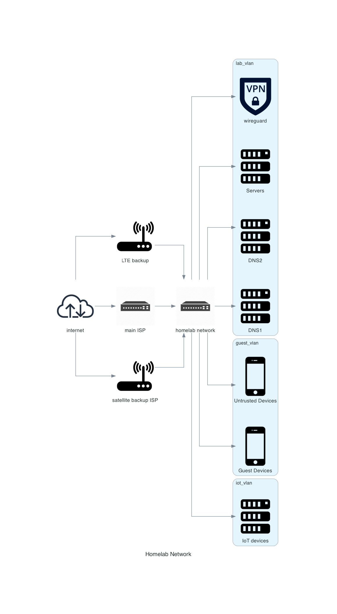
My internet access is provided by two providers. First provider is through copper coax (known as “cable” sometimes in the USA) and includes cellular LTE backup connection. Second provider is through satellite for access when there is no power in the neighborhood and potentially no LTE connection. I live in a mountainous region that experiences high winds, hail, and snow throughout the year.

This is a basic network diagram.
Network Devices

This is a diagram showing network devices that support the infrastructure.